5/20/2014
Arduino pro mini 5v 3.3 v - bootloader, write AVR MKII
Arduino pro mini bootloader write AVR MKII
- Avr Studio 4.18
- Attached avr mkii on Win7 64.
AVR MKII driver install. ( not libusb driver )
Your Installed Dir Arduino Sketch \
Arduino\
arduino-1.5.6-r2-windows\
arduino-1.5.6-r2\
hardware\
arduino\
avr\
bootloaders
Boot Loader Hex file Pro mini 5V/16MHz
reference from boards.txt ( arduino-1.5.6-r2-windows\arduino-1.5.6-r2\hardware\arduino\avr )
pro.menu.cpu.16MHzatmega328.bootloader.file=atmega/ATmegaBOOT_168_atmega328.hex
5/18/2014
OV7670 Pin Map
OV7670 CAMERA
Arduino ov7670 reference.
16 pin module.
20 pin ? other module.
http://forum.arduino.cc/index.php?PHPSESSID=ltg6b5m1pr6qs956c93k66qc42&topic=159557.0
https://gist.github.com/youngsoonpark/ed893de73026a450b99f| Description | Name | OV7670 pin | |
|---|---|---|---|
| VCC | +V | 1 | |
| Ground | GND | 2 | |
| SCCB CLK | SCL | 3 | |
| SCCB Data | SDA | 4 | |
| Vertical synchronization | VSYNC | 5 | |
| Line synchronization | HREF | 6 | |
| FIFO Write Enable | WEN | 7 | |
| XCK | XCK | 8 | |
| FIFO read address reset | RRST | 9 | |
| FIFO chip enable | OE | 10 | |
| FIFO read clock | RCLK | 11 | |
| Ground | GND | 12 | |
| FIFO output data | D0 | 13 | |
| FIFO output data | D1 | 14 | |
| FIFO output data | D2 | 15 | |
| FIFO output data | D3 | 16 | |
| FIFO output data | D4 | 17 | |
| FIFO output data | D5 | 18 | |
| FIFO output data | D6 | 19 | |
| FIFO output data | D7 | 20 |
5/09/2014
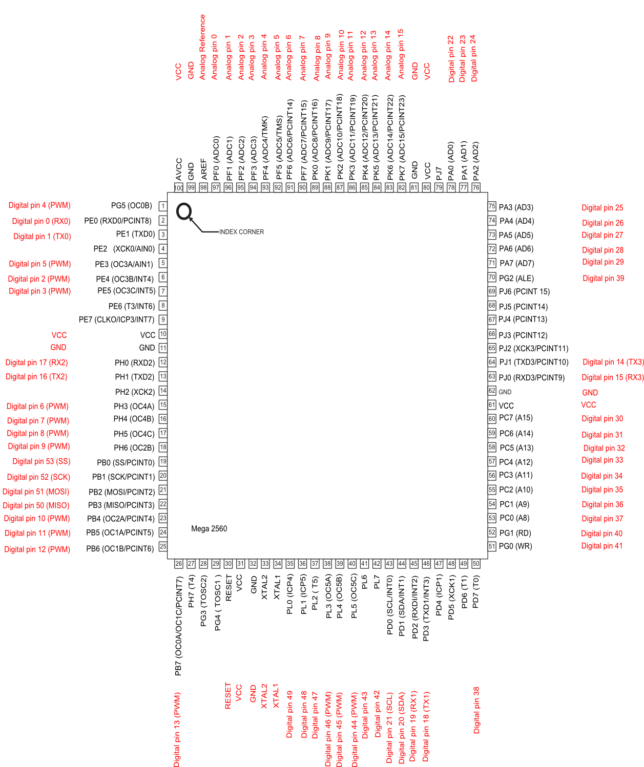
Arduino Mega 2560 pin map
ATmega2560-Arduino Pin Mapping
Below is the pin mapping for the Atmega2560. The chip used in Arduino 2560. There are pin mappings to Atmega8 and Atmega 168/328 as well.
Arduino Mega 2560 PIN diagram
Arduino Mega 2560 PIN mapping table
| Pin Number | Pin Name | Mapped Pin Name |
|---|---|---|
| 1 | PG5 ( OC0B ) | Digital pin 4 (PWM) |
| 2 | PE0 ( RXD0/PCINT8 ) | Digital pin 0 (RX0) |
| 3 | PE1 ( TXD0 ) | Digital pin 1 (TX0) |
| 4 | PE2 ( XCK0/AIN0 ) | |
| 5 | PE3 ( OC3A/AIN1 ) | Digital pin 5 (PWM) |
| 6 | PE4 ( OC3B/INT4 ) | Digital pin 2 (PWM) |
| 7 | PE5 ( OC3C/INT5 ) | Digital pin 3 (PWM) |
| 8 | PE6 ( T3/INT6 ) | |
| 9 | PE7 ( CLKO/ICP3/INT7 ) | |
| 10 | VCC | VCC |
| 11 | GND | GND |
| 12 | PH0 ( RXD2 ) | Digital pin 17 (RX2) |
| 13 | PH1 ( TXD2 ) | Digital pin 16 (TX2) |
| 14 | PH2 ( XCK2 ) | |
| 15 | PH3 ( OC4A ) | Digital pin 6 (PWM) |
| 16 | PH4 ( OC4B ) | Digital pin 7 (PWM) |
| 17 | PH5 ( OC4C ) | Digital pin 8 (PWM) |
| 18 | PH6 ( OC2B ) | Digital pin 9 (PWM) |
| 19 | PB0 ( SS/PCINT0 ) | Digital pin 53 (SS) |
| 20 | PB1 ( SCK/PCINT1 ) | Digital pin 52 (SCK) |
| 21 | PB2 ( MOSI/PCINT2 ) | Digital pin 51 (MOSI) |
| 22 | PB3 ( MISO/PCINT3 ) | Digital pin 50 (MISO) |
| 23 | PB4 ( OC2A/PCINT4 ) | Digital pin 10 (PWM) |
| 24 | PB5 ( OC1A/PCINT5 ) | Digital pin 11 (PWM) |
| 25 | PB6 ( OC1B/PCINT6 ) | Digital pin 12 (PWM) |
| 26 | PB7 ( OC0A/OC1C/PCINT7 ) | Digital pin 13 (PWM) |
| 27 | PH7 ( T4 ) | |
| 28 | PG3 ( TOSC2 ) | |
| 29 | PG4 ( TOSC1 ) | |
| 30 | RESET | RESET |
| 31 | VCC | VCC |
| 32 | GND | GND |
| 33 | XTAL2 | XTAL2 |
| 34 | XTAL1 | XTAL1 |
| 35 | PL0 ( ICP4 ) | Digital pin 49 |
| 36 | PL1 ( ICP5 ) | Digital pin 48 |
| 37 | PL2 ( T5 ) | Digital pin 47 |
| 38 | PL3 ( OC5A ) | Digital pin 46 (PWM) |
| 39 | PL4 ( OC5B ) | Digital pin 45 (PWM) |
| 40 | PL5 ( OC5C ) | Digital pin 44 (PWM) |
| 41 | PL6 | Digital pin 43 |
| 42 | PL7 | Digital pin 42 |
| 43 | PD0 ( SCL/INT0 ) | Digital pin 21 (SCL) |
| 44 | PD1 ( SDA/INT1 ) | Digital pin 20 (SDA) |
| 45 | PD2 ( RXDI/INT2 ) | Digital pin 19 (RX1) |
| 46 | PD3 ( TXD1/INT3 ) | Digital pin 18 (TX1) |
| 47 | PD4 ( ICP1 ) | |
| 48 | PD5 ( XCK1 ) | |
| 49 | PD6 ( T1 ) | |
| 50 | PD7 ( T0 ) | Digital pin 38 |
| 51 | PG0 ( WR ) | Digital pin 41 |
| 52 | PG1 ( RD ) | Digital pin 40 |
| 53 | PC0 ( A8 ) | Digital pin 37 |
| 54 | PC1 ( A9 ) | Digital pin 36 |
| 55 | PC2 ( A10 ) | Digital pin 35 |
| 56 | PC3 ( A11 ) | Digital pin 34 |
| 57 | PC4 ( A12 ) | Digital pin 33 |
| 58 | PC5 ( A13 ) | Digital pin 32 |
| 59 | PC6 ( A14 ) | Digital pin 31 |
| 60 | PC7 ( A15 ) | Digital pin 30 |
| 61 | VCC | VCC |
| 62 | GND | GND |
| 63 | PJ0 ( RXD3/PCINT9 ) | Digital pin 15 (RX3) |
| 64 | PJ1 ( TXD3/PCINT10 ) | Digital pin 14 (TX3) |
| 65 | PJ2 ( XCK3/PCINT11 ) | |
| 66 | PJ3 ( PCINT12 ) | |
| 67 | PJ4 ( PCINT13 ) | |
| 68 | PJ5 ( PCINT14 ) | |
| 69 | PJ6 ( PCINT 15 ) | |
| 70 | PG2 ( ALE ) | Digital pin 39 |
| 71 | PA7 ( AD7 ) | Digital pin 29 |
| 72 | PA6 ( AD6 ) | Digital pin 28 |
| 73 | PA5 ( AD5 ) | Digital pin 27 |
| 74 | PA4 ( AD4 ) | Digital pin 26 |
| 75 | PA3 ( AD3 ) | Digital pin 25 |
| 76 | PA2 ( AD2 ) | Digital pin 24 |
| 77 | PA1 ( AD1 ) | Digital pin 23 |
| 78 | PA0 ( AD0 ) | Digital pin 22 |
| 79 | PJ7 | |
| 80 | VCC | VCC |
| 81 | GND | GND |
| 82 | PK7 ( ADC15/PCINT23 ) | Analog pin 15 |
| 83 | PK6 ( ADC14/PCINT22 ) | Analog pin 14 |
| 84 | PK5 ( ADC13/PCINT21 ) | Analog pin 13 |
| 85 | PK4 ( ADC12/PCINT20 ) | Analog pin 12 |
| 86 | PK3 ( ADC11/PCINT19 ) | Analog pin 11 |
| 87 | PK2 ( ADC10/PCINT18 ) | Analog pin 10 |
| 88 | PK1 ( ADC9/PCINT17 ) | Analog pin 9 |
| 89 | PK0 ( ADC8/PCINT16 ) | Analog pin 8 |
| 90 | PF7 ( ADC7 ) | Analog pin 7 |
| 91 | PF6 ( ADC6 ) | Analog pin 6 |
| 92 | PF5 ( ADC5/TMS ) | Analog pin 5 |
| 93 | PF4 ( ADC4/TMK ) | Analog pin 4 |
| 94 | PF3 ( ADC3 ) | Analog pin 3 |
| 95 | PF2 ( ADC2 ) | Analog pin 2 |
| 96 | PF1 ( ADC1 ) | Analog pin 1 |
| 97 | PF0 ( ADC0 ) | Analog pin 0 |
| 98 | AREF | Analog Reference |
| 99 | GND | GND |
| 100 |
5/07/2014
rfcomm server example c linux
$ gcc rfcomm-server.c -lbluetooth
$ ./a.out
#include
#include
#include
#include
#include
int main(int argc, char **argv)
{
struct sockaddr_rc loc_addr = { 0 }, rem_addr = { 0 };
char buf[1024] = { 0 };
int s, client, bytes_read;
socklen_t opt = sizeof(rem_addr);
// allocate socket
s = socket(AF_BLUETOOTH, SOCK_STREAM, BTPROTO_RFCOMM);
// bind socket to port 1 of the first available
// local bluetooth adapter
loc_addr.rc_family = AF_BLUETOOTH;
loc_addr.rc_bdaddr = *BDADDR_ANY;
loc_addr.rc_channel = (uint8_t) 15;
bind(s, (struct sockaddr *)&loc_addr, sizeof(loc_addr));
// put socket into listening mode
listen(s, 1);
client=0; // initialize connection handle.
while(1)
{
if( client == 0 )
{
// accept one connection
printf("accept wait\n");
client = accept(s, (struct sockaddr *)&rem_addr, &opt);
printf("now accept %d\n",client);
ba2str( &rem_addr.rc_bdaddr, buf );
fprintf(stderr, "accepted connection from %s\n", buf);
memset(buf, 0, sizeof(buf));
}
// read data from the client
bytes_read = read(client, buf, sizeof(buf));
if( bytes_read > 0 )
{
printf("received [%s]\n", buf);
}
else
if( bytes_read < 0 )
{
close(client);
client=0;
printf("close connection\n");
}
printf("bytes_read [%d]\n",bytes_read);
}
// close connection
close(client);
close(s);
return 0;
}
5/02/2014
Bitwise Tips and Tricks - From
Below from http://www.opensourceforu.com/2012/06/power-programming-bitwise-tips-tricks/
Bitwise Tips and Tricks

If you are a seasoned programmer, these tips and tricks will seem very familiar, and are probably already part of your repertoire. If you are a novice programmer or a student, they should help you experience an “Aha!” moment. Independent of what you currently do, these tips and tricks will remind you of the wonderful discoveries in computer science, and the brilliant men and women behind them.
Before we get started, let’s establish some conventions for the rest of the article. Figure 1 shows how we represent bits — we start from right to left. The rightmost bit is the “Least Significant Bit” (LSB), and labelled as b0. The “Most Significant Bit” (MSB) is labelled b7. We use 8 bits to indicate and demonstrate concepts. The concept, however, is generically applicable to 32, 64, and even more bits.
Figure 1: Typical bit-wise representation
Population count
Population count refers to the number of bits that are set to 1. Typical uses of population counting are:- Single-bit parity generation and detection: To generate the correct parity bit, depending on the scheme being followed (odd or even parity), one would need to count the number of bits set to 1, and generate the corresponding bit for parity. Similarly, to check the parity of a block of bits, we would need to check the number of 1s, and validate the block against the expected parity setting.
- Hamming weight: Hamming weight is used in several fields, ranging from cryptography to information theory. The hamming distance between two strings A and B can be computed as the hamming weight of “A” XOR “B”.
First implementation
Our first implementation is the most straightforward:int count_ones(int num){ int count = 0; int mask = 0x1; while (num) { if (num & mask) count++; num >>= 1; } return count;} |
Improving the algorithm
For those familiar with design techniques like divide and conquer, the idea below is a classical trick called the “Gillies-Miller method for sideways addition”. This process is shown in Figure 2.
Figure 2: Divide and conquer the summation of bits
static inline unsigned char bit_count(unsigned char x){ x = (0x55 & x) + (0x55 & (x >> 1)); x = (0x33 & x) + (0x33 & (x >> 2)); x = (0x0f & x) + (0x0f & (x >> 4)); return x;} |
- It uses a mask at each step in the algorithm.
- The code takes O(log n) time to complete.

Figure 3: Masks to divide and conquer summation
This procedure is repeated; the goal now is to compute the sum of the intermediate result obtained in the step above. The previous step counted the sum of alternate bits; it is now time to sum two bits at a time. The corresponding mask for this step is 0×33 (can you see why?). Again, we repeat the procedure by masking the number with 0×33, and adding to it the result of the number right-shifted by 2 and masked by 0×33. We do something similar in the final step, where we need to count 4 bits at a time, and sum up the result to obtain the final answer.
Figure 2 shows a sample computation for the number 177, which is represented as 10110001.
In Step 1, we sum the adjacent bits, leading to 01100001 (the sum of 1 and 0 is 01, the sum of 1 and 1 is 10 (in binary, this represents 2), the sum of 0 and 0 is 00, the sum of 0 and 1 is 01). In the next step, we sum 2 bits at a time, resulting in 00110001 (the sum of 01 and 10 is 0011 — 3 in binary; the sum of 00 and 01 is 0001).
In the final step, we sum 4 bits at a time, resulting in 00000100 (the sum of 0011 and 0001 is 00000100 — 4 in binary). As expected, this is also the final outcome, and the result of the number of 1s in the block under consideration.
This completes the sideways addition algorithm. As you can see, this algorithm is clearly more efficient than the initial approach.
Exercises
- We focused on 8 bits in a block to explain the algorithm. This algorithm can easily be extended to 32 or 64 bits and beyond. Write a routine to extend this algorithm to 64 bits, and potentially all the way up to 256 bits.
- The algorithm specified above (in the section Improving the algorithm) is not necessarily optimal. Look at the references below to see if a more optimal version can be found and used. Explain what optimisations are possible, and how.
References
- •MMIXware: A RISC Computer for the Third Millennium by Donald E Knuth, Springer-Verlag, 1999
- •Matters Computational: ideas, algorithms, source code by Jorg Arndt, Draft version of 20-June-2010
This article was originally published in September 2010 issue of the print magazine
피드 구독하기:
글 (Atom)