Library Example:
'via Blog this'
6/05/2014
6/03/2014
Explain Arduino Mega 2560 R3 pins

Input and Output
Each of the 54 digital pins on the Arduino 2560 Mega can be used as an input or output, using pinMode(), digitalWrite(), and digitalRead() functions. They operate at 5 volts. Each pin can provide or receive a maximum of 40 mA and has an internal pull-up resistor (disconnected by default) of 20-50 kOhms.
In addition, some pins have specialized functions:
Serial: 0 (RX) and 1 (TX);
Serial 1: 19 (RX) and 18 (TX);
Serial 2: 17 (RX) and 16 (TX);
Serial 3: 15 (RX) and 14 (TX).
Used to receive (RX) and transmit (TX) TTL serial data. Pins 0 and 1 are also connected to the corresponding pins of the ATmega16U2 USB-to-TTL Serial chip.
External Interrupts: 2 (interrupt 0), 3 (interrupt 1), 18 (interrupt 5), 19 (interrupt 4), 20 (interrupt 3), and 21 (interrupt 2). These pins can be configured to trigger an interrupt on a low value, a rising or falling edge, or a change in value. See the attachInterrupt() function for details.
PWM: 2 to 13 and 44 to 46. Provide 8-bit PWM output with the analogWrite() function.
SPI: 50 (MISO), 51 (MOSI), 52 (SCK), 53 (SS). These pins support SPI communication using the SPI library. The SPI pins are also broken out on the ICSP header, which is physically compatible with the Uno, Duemilanove and Diecimila.
LED: 13. There is a built-in LED connected to digital pin 13. When the pin is HIGH value, the LED is on, when the pin is LOW, it’s off.
TWI: 20 (SDA) and 21 (SCL). Support TWI communication using the Wire library. Note that these pins are not in the same location as the TWI pins on the Duemilanove or Diecimila.
The Mega2560 has 16 analog inputs, each of which provide 10 bits of resolution (i.e. 1024 different values). By default they measure from ground to 5 volts, though is it possible to change the upper end of their range using the AREF pin and analogReference() function.
There are a couple of other pins on the board:
AREF. Reference voltage for the analog inputs. Used with analogReference().
Reset. Bring this line LOW to reset the microcontroller. Typically used to add a reset button to shields which block the one on the board.
5/25/2014
UIPEthernet EchoServer example and test
Below example code. from UIPEthernet library.
/*
* UIPEthernet EchoServer example.
*
* UIPEthernet is a TCP/IP stack that can be used with a enc28j60 based
* Ethernet-shield.
*
* UIPEthernet uses the fine uIP stack by Adam Dunkels <adam@sics.se>
*
* -----------------
*
* This Hello World example sets up a server at 192.168.1.6 on port 1000.
* Telnet here to access the service. The uIP stack will also respond to
* pings to test if you have successfully established a TCP connection to
* the Arduino.
*
* This example was based upon uIP hello-world by Adam Dunkels <adam@sics.se>
* Ported to the Arduino IDE by Adam Nielsen <malvineous@shikadi.net>
* Adaption to Enc28J60 by Norbert Truchsess <norbert.truchsess@t-online.de>
*/
#include
// The connection_data struct needs to be defined in an external file.
#include
#include
EthernetServer server = EthernetServer(1000);
void setup()
{
Serial.begin(9600);
uint8_t mac[6] = {0x00,0x01,0x02,0x03,0x04,0x05};
IPAddress myIP(192,168,1,177);
Ethernet.begin(mac,myIP);
server.begin();
}
void loop()
{
size_t size;
if (EthernetClient client = server.available())
{
if (client)
{
while((size = client.available()) > 0)
{
uint8_t* msg = (uint8_t*)malloc(size);
size = client.read(msg,size);
Serial.write(msg,size);
client.write(msg,size);
free(msg);
}
}
}
}
Testing.
$ telnet 192.168.1.177 1000
Trying 192.168.1.177...
Connected to 192.168.1.177.
Escape character is '^]'.
( typing keyboard ... for test )
5/24/2014
Arduino pro mini 3.3v 8MHz or 5V 16 MHz - ENC28J60 SPI wire pin map.
ENC28J60 SPI
Arduino pro mini 3.3v - VCC no ohm.
Arduino pro mini 5v = VCC 10 ohm
| Mini Ethernet Module | Arduino Pro Mini |
| GND | GND |
| 3.3V | 3.3V ( 250 mA, VDD = 3.45V, FCLK =10 MHz, SO = open ) |
| RESET | not connected - or connect. |
| CLKOUT | not connected |
| INT | PIN 3 |
| W0L | not connected |
| S0 | PIN 12 |
| SI | PIN 11 |
| SCK | PIN 13 |
| CS | PIN 8 or PIN 10 |
| --- | --- |
5/20/2014
Ubuntu, Raspberry Pi,CubieBoard Linux A2DP, bluetooth audio source receiver service, speaker
Bluetooth A2DP receiver.
$ sudo apt-get install pulseaudio-module-bluetooth$ pactl load-module module-loopback source_dont_move=yes source=$BTSOURCE sink=$SINK
- You can find $SINK with $
pactl list sinks, $SINK is shown after Name:
- And you can see the $BTSOURCE with $
pactl list sources
$ pactl load-module module-loopback source_dont_move=yes source=bluez_source.9C_E6_E7_C8_B2_A3 sink=alsa_output.platform-bcm2835_AUD0.0.analog-stereo
ex) Play audio from Smartphone
Find pulseaudio source list $ pactl list sourcesSource #0
State: IDLE
Name: alsa_output.platform-bcm2835_AUD0.0.analog-stereo.monitor
Description: Monitor of bcm2835 ALSA Analog Stereo
Driver: module-alsa-card.c
Sample Specification: s16le 2ch 44100Hz
Channel Map: front-left,front-right
Owner Module: 4
Mute: no
Volume: 0: 100% 1: 100%
0: 0.00 dB 1: 0.00 dB
balance 0.00
Base Volume: 100%
0.00 dB
Monitor of Sink: alsa_output.platform-bcm2835_AUD0.0.analog-stereo
Latency: 0 usec, configured 371519 usec
Flags: DECIBEL_VOLUME LATENCY
Properties:
device.description = "Monitor of bcm2835 ALSA Analog Stereo"
device.class = "monitor"
alsa.card = "0"
alsa.card_name = "bcm2835 ALSA"
alsa.long_card_name = "bcm2835 ALSA"
alsa.driver_name = "snd_bcm2835"
device.bus_path = "platform-bcm2835_AUD0.0"
sysfs.path = "/devices/platform/bcm2835_AUD0.0/sound/card0"
device.string = "0"
module-udev-detect.discovered = "1"
device.icon_name = "audio-card"
Formats:
pcm
Source #2
State: RUNNING
Name: bluez_source.9C_E6_E7_C8_B2_A3
Description: SHW-M440S
Driver: module-bluetooth-device.c
Sample Specification: s16le 2ch 44100Hz
Channel Map: front-left,front-right
Owner Module: 25
Mute: no
Volume: 0: 100% 1: 100%
0: 0.00 dB 1: 0.00 dB
balance 0.00
Base Volume: 100%
0.00 dB
Monitor of Sink: n/a
Latency: 198393 usec, configured 193344 usec
Flags: HARDWARE DECIBEL_VOLUME LATENCY
Properties:
bluetooth.protocol = "a2dp_source"
device.description = "SHW-M440S"
device.string = "9C:E6:E7:C8:B2:A3"
device.api = "bluez"
device.class = "sound"
device.bus = "bluetooth"
bluez.path = "/org/bluez/2163/hci0/dev_9C_E6_E7_C8_B2_A3"
bluez.class = "0x5a020c"
bluez.name = "SHW-M440S"
device.icon_name = "audio-card-bluetooth"
Formats:
pcmArduino pro mini 5v 3.3 v - bootloader, write AVR MKII
Arduino pro mini bootloader write AVR MKII
- Avr Studio 4.18
- Attached avr mkii on Win7 64.
AVR MKII driver install. ( not libusb driver )
Your Installed Dir Arduino Sketch \
Arduino\
arduino-1.5.6-r2-windows\
arduino-1.5.6-r2\
hardware\
arduino\
avr\
bootloaders
Boot Loader Hex file Pro mini 5V/16MHz
reference from boards.txt ( arduino-1.5.6-r2-windows\arduino-1.5.6-r2\hardware\arduino\avr )
pro.menu.cpu.16MHzatmega328.bootloader.file=atmega/ATmegaBOOT_168_atmega328.hex
5/18/2014
OV7670 Pin Map
OV7670 CAMERA
Arduino ov7670 reference.
16 pin module.
20 pin ? other module.
http://forum.arduino.cc/index.php?PHPSESSID=ltg6b5m1pr6qs956c93k66qc42&topic=159557.0
https://gist.github.com/youngsoonpark/ed893de73026a450b99f| Description | Name | OV7670 pin | |
|---|---|---|---|
| VCC | +V | 1 | |
| Ground | GND | 2 | |
| SCCB CLK | SCL | 3 | |
| SCCB Data | SDA | 4 | |
| Vertical synchronization | VSYNC | 5 | |
| Line synchronization | HREF | 6 | |
| FIFO Write Enable | WEN | 7 | |
| XCK | XCK | 8 | |
| FIFO read address reset | RRST | 9 | |
| FIFO chip enable | OE | 10 | |
| FIFO read clock | RCLK | 11 | |
| Ground | GND | 12 | |
| FIFO output data | D0 | 13 | |
| FIFO output data | D1 | 14 | |
| FIFO output data | D2 | 15 | |
| FIFO output data | D3 | 16 | |
| FIFO output data | D4 | 17 | |
| FIFO output data | D5 | 18 | |
| FIFO output data | D6 | 19 | |
| FIFO output data | D7 | 20 |
5/09/2014
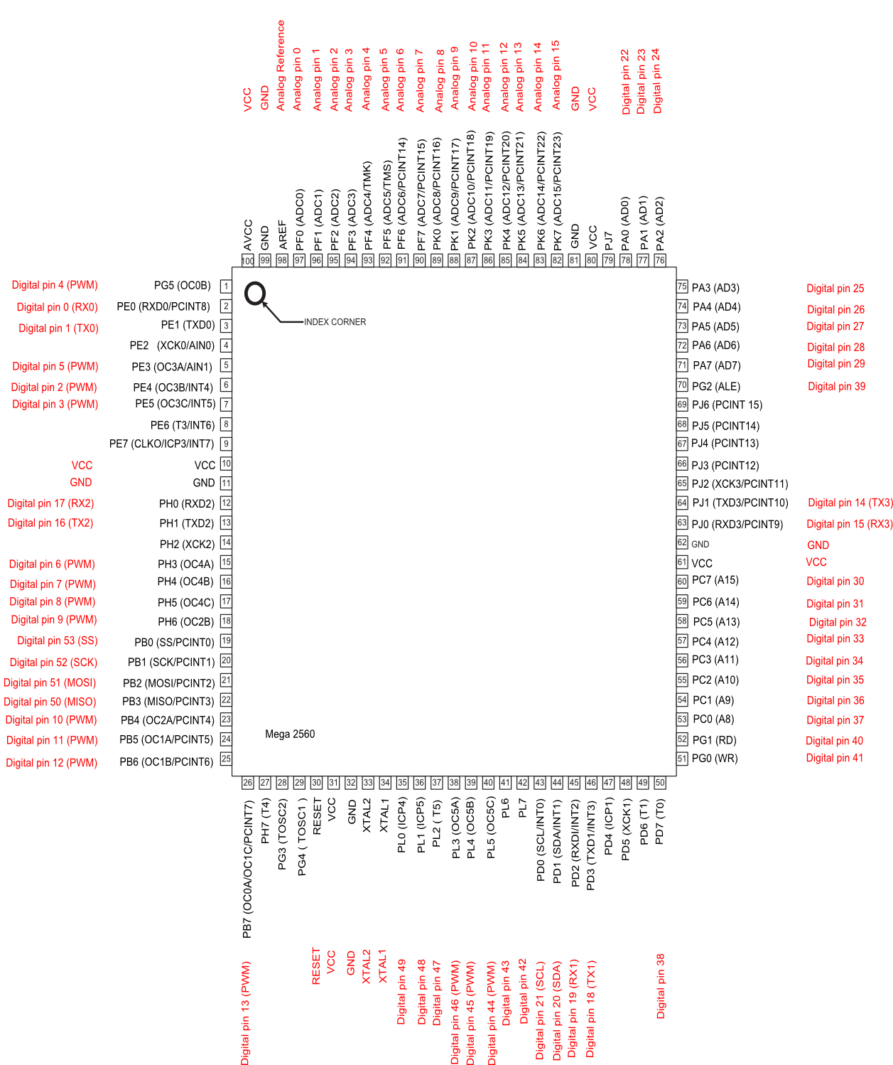
Arduino Mega 2560 pin map
ATmega2560-Arduino Pin Mapping
Below is the pin mapping for the Atmega2560. The chip used in Arduino 2560. There are pin mappings to Atmega8 and Atmega 168/328 as well.
Arduino Mega 2560 PIN diagram
Arduino Mega 2560 PIN mapping table
| Pin Number | Pin Name | Mapped Pin Name |
|---|---|---|
| 1 | PG5 ( OC0B ) | Digital pin 4 (PWM) |
| 2 | PE0 ( RXD0/PCINT8 ) | Digital pin 0 (RX0) |
| 3 | PE1 ( TXD0 ) | Digital pin 1 (TX0) |
| 4 | PE2 ( XCK0/AIN0 ) | |
| 5 | PE3 ( OC3A/AIN1 ) | Digital pin 5 (PWM) |
| 6 | PE4 ( OC3B/INT4 ) | Digital pin 2 (PWM) |
| 7 | PE5 ( OC3C/INT5 ) | Digital pin 3 (PWM) |
| 8 | PE6 ( T3/INT6 ) | |
| 9 | PE7 ( CLKO/ICP3/INT7 ) | |
| 10 | VCC | VCC |
| 11 | GND | GND |
| 12 | PH0 ( RXD2 ) | Digital pin 17 (RX2) |
| 13 | PH1 ( TXD2 ) | Digital pin 16 (TX2) |
| 14 | PH2 ( XCK2 ) | |
| 15 | PH3 ( OC4A ) | Digital pin 6 (PWM) |
| 16 | PH4 ( OC4B ) | Digital pin 7 (PWM) |
| 17 | PH5 ( OC4C ) | Digital pin 8 (PWM) |
| 18 | PH6 ( OC2B ) | Digital pin 9 (PWM) |
| 19 | PB0 ( SS/PCINT0 ) | Digital pin 53 (SS) |
| 20 | PB1 ( SCK/PCINT1 ) | Digital pin 52 (SCK) |
| 21 | PB2 ( MOSI/PCINT2 ) | Digital pin 51 (MOSI) |
| 22 | PB3 ( MISO/PCINT3 ) | Digital pin 50 (MISO) |
| 23 | PB4 ( OC2A/PCINT4 ) | Digital pin 10 (PWM) |
| 24 | PB5 ( OC1A/PCINT5 ) | Digital pin 11 (PWM) |
| 25 | PB6 ( OC1B/PCINT6 ) | Digital pin 12 (PWM) |
| 26 | PB7 ( OC0A/OC1C/PCINT7 ) | Digital pin 13 (PWM) |
| 27 | PH7 ( T4 ) | |
| 28 | PG3 ( TOSC2 ) | |
| 29 | PG4 ( TOSC1 ) | |
| 30 | RESET | RESET |
| 31 | VCC | VCC |
| 32 | GND | GND |
| 33 | XTAL2 | XTAL2 |
| 34 | XTAL1 | XTAL1 |
| 35 | PL0 ( ICP4 ) | Digital pin 49 |
| 36 | PL1 ( ICP5 ) | Digital pin 48 |
| 37 | PL2 ( T5 ) | Digital pin 47 |
| 38 | PL3 ( OC5A ) | Digital pin 46 (PWM) |
| 39 | PL4 ( OC5B ) | Digital pin 45 (PWM) |
| 40 | PL5 ( OC5C ) | Digital pin 44 (PWM) |
| 41 | PL6 | Digital pin 43 |
| 42 | PL7 | Digital pin 42 |
| 43 | PD0 ( SCL/INT0 ) | Digital pin 21 (SCL) |
| 44 | PD1 ( SDA/INT1 ) | Digital pin 20 (SDA) |
| 45 | PD2 ( RXDI/INT2 ) | Digital pin 19 (RX1) |
| 46 | PD3 ( TXD1/INT3 ) | Digital pin 18 (TX1) |
| 47 | PD4 ( ICP1 ) | |
| 48 | PD5 ( XCK1 ) | |
| 49 | PD6 ( T1 ) | |
| 50 | PD7 ( T0 ) | Digital pin 38 |
| 51 | PG0 ( WR ) | Digital pin 41 |
| 52 | PG1 ( RD ) | Digital pin 40 |
| 53 | PC0 ( A8 ) | Digital pin 37 |
| 54 | PC1 ( A9 ) | Digital pin 36 |
| 55 | PC2 ( A10 ) | Digital pin 35 |
| 56 | PC3 ( A11 ) | Digital pin 34 |
| 57 | PC4 ( A12 ) | Digital pin 33 |
| 58 | PC5 ( A13 ) | Digital pin 32 |
| 59 | PC6 ( A14 ) | Digital pin 31 |
| 60 | PC7 ( A15 ) | Digital pin 30 |
| 61 | VCC | VCC |
| 62 | GND | GND |
| 63 | PJ0 ( RXD3/PCINT9 ) | Digital pin 15 (RX3) |
| 64 | PJ1 ( TXD3/PCINT10 ) | Digital pin 14 (TX3) |
| 65 | PJ2 ( XCK3/PCINT11 ) | |
| 66 | PJ3 ( PCINT12 ) | |
| 67 | PJ4 ( PCINT13 ) | |
| 68 | PJ5 ( PCINT14 ) | |
| 69 | PJ6 ( PCINT 15 ) | |
| 70 | PG2 ( ALE ) | Digital pin 39 |
| 71 | PA7 ( AD7 ) | Digital pin 29 |
| 72 | PA6 ( AD6 ) | Digital pin 28 |
| 73 | PA5 ( AD5 ) | Digital pin 27 |
| 74 | PA4 ( AD4 ) | Digital pin 26 |
| 75 | PA3 ( AD3 ) | Digital pin 25 |
| 76 | PA2 ( AD2 ) | Digital pin 24 |
| 77 | PA1 ( AD1 ) | Digital pin 23 |
| 78 | PA0 ( AD0 ) | Digital pin 22 |
| 79 | PJ7 | |
| 80 | VCC | VCC |
| 81 | GND | GND |
| 82 | PK7 ( ADC15/PCINT23 ) | Analog pin 15 |
| 83 | PK6 ( ADC14/PCINT22 ) | Analog pin 14 |
| 84 | PK5 ( ADC13/PCINT21 ) | Analog pin 13 |
| 85 | PK4 ( ADC12/PCINT20 ) | Analog pin 12 |
| 86 | PK3 ( ADC11/PCINT19 ) | Analog pin 11 |
| 87 | PK2 ( ADC10/PCINT18 ) | Analog pin 10 |
| 88 | PK1 ( ADC9/PCINT17 ) | Analog pin 9 |
| 89 | PK0 ( ADC8/PCINT16 ) | Analog pin 8 |
| 90 | PF7 ( ADC7 ) | Analog pin 7 |
| 91 | PF6 ( ADC6 ) | Analog pin 6 |
| 92 | PF5 ( ADC5/TMS ) | Analog pin 5 |
| 93 | PF4 ( ADC4/TMK ) | Analog pin 4 |
| 94 | PF3 ( ADC3 ) | Analog pin 3 |
| 95 | PF2 ( ADC2 ) | Analog pin 2 |
| 96 | PF1 ( ADC1 ) | Analog pin 1 |
| 97 | PF0 ( ADC0 ) | Analog pin 0 |
| 98 | AREF | Analog Reference |
| 99 | GND | GND |
| 100 |
5/07/2014
rfcomm server example c linux
$ gcc rfcomm-server.c -lbluetooth
$ ./a.out
#include
#include
#include
#include
#include
int main(int argc, char **argv)
{
struct sockaddr_rc loc_addr = { 0 }, rem_addr = { 0 };
char buf[1024] = { 0 };
int s, client, bytes_read;
socklen_t opt = sizeof(rem_addr);
// allocate socket
s = socket(AF_BLUETOOTH, SOCK_STREAM, BTPROTO_RFCOMM);
// bind socket to port 1 of the first available
// local bluetooth adapter
loc_addr.rc_family = AF_BLUETOOTH;
loc_addr.rc_bdaddr = *BDADDR_ANY;
loc_addr.rc_channel = (uint8_t) 15;
bind(s, (struct sockaddr *)&loc_addr, sizeof(loc_addr));
// put socket into listening mode
listen(s, 1);
client=0; // initialize connection handle.
while(1)
{
if( client == 0 )
{
// accept one connection
printf("accept wait\n");
client = accept(s, (struct sockaddr *)&rem_addr, &opt);
printf("now accept %d\n",client);
ba2str( &rem_addr.rc_bdaddr, buf );
fprintf(stderr, "accepted connection from %s\n", buf);
memset(buf, 0, sizeof(buf));
}
// read data from the client
bytes_read = read(client, buf, sizeof(buf));
if( bytes_read > 0 )
{
printf("received [%s]\n", buf);
}
else
if( bytes_read < 0 )
{
close(client);
client=0;
printf("close connection\n");
}
printf("bytes_read [%d]\n",bytes_read);
}
// close connection
close(client);
close(s);
return 0;
}
5/02/2014
Bitwise Tips and Tricks - From
Below from http://www.opensourceforu.com/2012/06/power-programming-bitwise-tips-tricks/
Bitwise Tips and Tricks

If you are a seasoned programmer, these tips and tricks will seem very familiar, and are probably already part of your repertoire. If you are a novice programmer or a student, they should help you experience an “Aha!” moment. Independent of what you currently do, these tips and tricks will remind you of the wonderful discoveries in computer science, and the brilliant men and women behind them.
Before we get started, let’s establish some conventions for the rest of the article. Figure 1 shows how we represent bits — we start from right to left. The rightmost bit is the “Least Significant Bit” (LSB), and labelled as b0. The “Most Significant Bit” (MSB) is labelled b7. We use 8 bits to indicate and demonstrate concepts. The concept, however, is generically applicable to 32, 64, and even more bits.
Figure 1: Typical bit-wise representation
Population count
Population count refers to the number of bits that are set to 1. Typical uses of population counting are:- Single-bit parity generation and detection: To generate the correct parity bit, depending on the scheme being followed (odd or even parity), one would need to count the number of bits set to 1, and generate the corresponding bit for parity. Similarly, to check the parity of a block of bits, we would need to check the number of 1s, and validate the block against the expected parity setting.
- Hamming weight: Hamming weight is used in several fields, ranging from cryptography to information theory. The hamming distance between two strings A and B can be computed as the hamming weight of “A” XOR “B”.
First implementation
Our first implementation is the most straightforward:int count_ones(int num){ int count = 0; int mask = 0x1; while (num) { if (num & mask) count++; num >>= 1; } return count;} |
Improving the algorithm
For those familiar with design techniques like divide and conquer, the idea below is a classical trick called the “Gillies-Miller method for sideways addition”. This process is shown in Figure 2.
Figure 2: Divide and conquer the summation of bits
static inline unsigned char bit_count(unsigned char x){ x = (0x55 & x) + (0x55 & (x >> 1)); x = (0x33 & x) + (0x33 & (x >> 2)); x = (0x0f & x) + (0x0f & (x >> 4)); return x;} |
- It uses a mask at each step in the algorithm.
- The code takes O(log n) time to complete.

Figure 3: Masks to divide and conquer summation
This procedure is repeated; the goal now is to compute the sum of the intermediate result obtained in the step above. The previous step counted the sum of alternate bits; it is now time to sum two bits at a time. The corresponding mask for this step is 0×33 (can you see why?). Again, we repeat the procedure by masking the number with 0×33, and adding to it the result of the number right-shifted by 2 and masked by 0×33. We do something similar in the final step, where we need to count 4 bits at a time, and sum up the result to obtain the final answer.
Figure 2 shows a sample computation for the number 177, which is represented as 10110001.
In Step 1, we sum the adjacent bits, leading to 01100001 (the sum of 1 and 0 is 01, the sum of 1 and 1 is 10 (in binary, this represents 2), the sum of 0 and 0 is 00, the sum of 0 and 1 is 01). In the next step, we sum 2 bits at a time, resulting in 00110001 (the sum of 01 and 10 is 0011 — 3 in binary; the sum of 00 and 01 is 0001).
In the final step, we sum 4 bits at a time, resulting in 00000100 (the sum of 0011 and 0001 is 00000100 — 4 in binary). As expected, this is also the final outcome, and the result of the number of 1s in the block under consideration.
This completes the sideways addition algorithm. As you can see, this algorithm is clearly more efficient than the initial approach.
Exercises
- We focused on 8 bits in a block to explain the algorithm. This algorithm can easily be extended to 32 or 64 bits and beyond. Write a routine to extend this algorithm to 64 bits, and potentially all the way up to 256 bits.
- The algorithm specified above (in the section Improving the algorithm) is not necessarily optimal. Look at the references below to see if a more optimal version can be found and used. Explain what optimisations are possible, and how.
References
- •MMIXware: A RISC Computer for the Third Millennium by Donald E Knuth, Springer-Verlag, 1999
- •Matters Computational: ideas, algorithms, source code by Jorg Arndt, Draft version of 20-June-2010
This article was originally published in September 2010 issue of the print magazine
4/22/2014
How To determine Linux Kernel Timer Interrupt Frequency
How To determine Linux Kernel Timer Interrupt Frequency
Linux timer interrupt frequency is an important parameter for near to real-time and multimedia applications running on Linux. The timer interrupt frequency directly impacts the capability of any near-to real time and multimedia application to process events at high frequencies. The term high in this context means usually greater than 100 Hz (10 ms).In the old days the kernel configuration setting CONFIG_HZ was the most important setting for the kernel timer frequency. It was defined at compilation time of the kernel and settings varied between distributions and kernel versions.
Today, a number of other kernel settings - such as NO_HZ, HIGH_RES_TIMERS - impact the kernel timer interrupt frequency as well. Finally the availability of High Precision Event Timer (HPET) support is also an important feature.
All these settings may be retrieved easily from the current kernel configuration. For example:
01 | $ cat /boot/config-`uname -r` | grep HZ |
02 | # CONFIG_HZ_1000 is not set |
03 | # CONFIG_HZ_300 is not set |
04 | CONFIG_MACHZ_WDT=m |
05 | CONFIG_NO_HZ=y |
06 | CONFIG_HZ=100 |
07 | CONFIG_HZ_100=y |
08 | # CONFIG_HZ_250 is not set |
09 |
10 | $ cat /boot/config-`uname -r` | grep HIGH_RES_TIMERS |
11 | CONFIG_HIGH_RES_TIMERS=y |
01 | #include |
02 | #include |
03 | #include |
04 | #include |
05 | #include |
06 |
07 |
08 | #define USECREQ 250 |
09 | #define LOOPS 1000 |
10 |
11 | void event_handler (int signum) |
12 | { |
13 | static unsigned long cnt = 0; |
14 | static struct timeval tsFirst; |
15 | if (cnt == 0) { |
16 | gettimeofday (&tsFirst, 0); |
17 | } |
18 | cnt ++; |
19 | if (cnt >= LOOPS) { |
20 | struct timeval tsNow; |
21 | struct timeval diff; |
22 | setitimer (ITIMER_REAL, NULL, NULL); |
23 | gettimeofday (&tsNow, 0); |
24 | timersub(&tsNow, &tsFirst, &diff); |
25 | unsigned long long udiff = (diff.tv_sec * 1000000) + diff.tv_usec; |
26 | double delta = (double)(udiff/cnt)/1000000; |
27 | int hz = (unsigned)(1.0/delta); |
28 | printf ("kernel timer interrupt frequency is approx. %d Hz", hz); |
29 | if (hz >= (int) (1.0/((double)(USECREQ)/1000000))) { |
30 | printf (" or higher"); |
31 | } |
32 | printf ("\n"); |
33 | exit (0); |
34 | } |
35 | } |
36 |
37 | int main (int argc, char **argv) |
38 | { |
39 | struct sigaction sa; |
40 | struct itimerval timer; |
41 |
42 | memset (&sa, 0, sizeof (sa)); |
43 | sa.sa_handler = &event_handler; |
44 | sigaction (SIGALRM, &sa, NULL); |
45 | timer.it_value.tv_sec = 0; |
46 | timer.it_value.tv_usec = USECREQ; |
47 | timer.it_interval.tv_sec = 0; |
48 | timer.it_interval.tv_usec = USECREQ; |
49 | setitimer (ITIMER_REAL, &timer, NULL); |
50 | while (1); |
51 | } |
- Create a local copy of this small program, as e.g. frequency-test.c
- Compile it with gcc: "gcc frequency-test.c"
- Run it: "./a.out"
1 | $ ./a.out |
2 | kernel timer interrupt frequency is approx. 4016 Hz or higher |
1 | $ ./a.out |
2 | kernel timer interrupt frequency is approx. 4016 Hz or higher |
1 | $ ./a.out |
2 | kernel timer interrupt frequency is approx. 249 Hz |
If the timer interrupt frequency determined on your system is for example around 250Hz, it will be very difficult for any near to real-time or multimedia application to send out an isochronous data stream of 250 packets per second (pps).
MS,US,NS,PS,FS,AS,FPS,HZ,MHZ
1. 컴퓨터의 처리 속도
ms : 밀리초 0.001 = 10^(-3)초
㎲ : 마이크로초 0.000001초 = 10^(-6)초
㎱: 나노초 0.000000001초 = 10^(-9)초
㎰ : 피코초 0.000000000001초 = 10^(-12)초
fs : 펨토초 0.000000000000001초 = 10^(-15)초
as : 아토초 0.000000000000000001초 = 10^(-18)초
여담으로,
보통 VGA메모리보면 2.8ns다 4ns다 이런식으로 메모리속도 표기를 하게됩니다.
ns(나노 초, 나노 세컨드)는 한 파장의 길이를 뜻합니다.
만약 4ns 의 램이 있다고 치면,
1s(초) = 1,000,000,000ns(나노 초) 니까, 1,000,000,000ns/4ns 하면 1s(초)안에 4ns(나노 초)가 250,000,000개 들어가는가지요.
그러면 Hz 는 1s(초)를 기준으로 하는 진동수이므로 250,000,000Hz 가 되지요.
결국 250,000,000Hz 를 단위 변환하여 메가 헤르츠(10^-6)로 바꾸면 250Mhz 가 되는것입니다.
그러니까 4ns = (1,000,000,000/4)/10^6 Hz = 250MHz 입니다.
ns와 MHz 사이의 관계를 공식으로 표현하면 x (ns) = 1,000/x (MHz) 가 되는겁니다.
오버클럭에도 적용할수 있는데, 만약 내 VGA램속도가 4ns라면 250MHz(DDR이면500MHz)까지는
정말 안정적으로 메모리클럭을 올릴수 있다는 얘기가 됩니다.
따라서 고급형 그래픽카드의 경우 ns가 낮은램을 써서 메모리클럭을 올려서 출시하는경우를 보실수 있을겁니다. 같은클럭이라도 ns가 낮은램이 오버클럭에 유리한건 당연지사입니다.
2. 컴퓨터의 기억 용량
1024byte = 1KB (kilo byte)
1024KB = 1MB (mega byte)
1024MB = 1GB (giga byte) = 1048576 KB
1024GB = 1TB (tela byte)
1024TB = 1PB (peta byte)
또 여담으로
200기가 짜리를 사서 포맷을 하면 200기가로 표기되지 않는이유가 여기에 있습니다.
보통제조사는 200,000,000,000바이트 용량의 하드를 200기가라고 표기하게 되는데
실제 1000으로 나뉘는게 아니라 1024로 나뉘므로 1024로 계속 나누면 186기가쯤으로 잡힙니다.
3. 자료의 표현 단위
Bit(비트) : Binary digit의 약자. 정보를 표현하는 최소 단위.
0 또는 1 : Binary digit (bit) 기록의 최소 단위
n개의 비트는 2n의 자료를 표시함.
nibble(니블) : 4비트로 이루어진 정보 표현의 단위.
Byte(바이트) : 8bit = 1byte로 문자표현의 최소 단위
8개의 비트로 256가지의 자료 표현이 가능함.(28 = 256)
영문 : 1 byte = 8bit
한글 : 2 byte = 16bit
Word(워드) : 몇 개의 바이트를 묶어서 이루어진 한 개의 기억단위.
하프워드 = 2바이트
풀워드 = 4바이트
더블워드 = 8바이트
Field (=Item. 필드) : 여러 개의 바이트나 워드가 모여 이루어진 정보 단위.
Record(레코드) : 프로그램 내의 자료 처리 단위.
Block(블록) : 자료의 입·출력의 기본 단위. 물리적 레코드.
File(파일) : 하나의 프로그램 처리 단위.
Data Base(데이터 베이스) : 계층적 구조를 갖는 자료 단위.
4. 단위에 관계된 여러 가지 용어
BUS : 32bit, 16bit, 64bit
bit란 한번에 전달해 주는 자료의 수. Bus를 따지는 용어.
PC속도 : KHz(킬로 헤르쯔) , MHz(메가 헤르쯔), GHz(기가 헤르쯔)
PC용량 : 하드의 용량 ex)1.2GB
참고 : 대역폭 계산
DDR400의 램인 경우(200*2)
400 * (64bit / 8bit) = 3200 MB/s = 3.2 GB/s
64를 8로 나눈 것은 바이트로 바꾸기 위한 것
펜티엄4 노스우드C인 경우(200*4)
800 * (32 / 8) = 3200 MB/s = 3.2 GB/s
한마디로 동작클럭에 비트수를 바이트로 변환하여 곱하면 됨.
printf - usage
function
printf
int printf ( const char * format, ... );
Print formatted data to stdout
Parameters
- format
- C string that contains the text to be written to stdout.
It can optionally contain embedded format specifiers that are replaced by the values specified in subsequent additional arguments and formatted as requested.
A format specifier follows this prototype: [see compatibility note below]
%[flags][width][.precision][length]specifier
Where the specifier character at the end is the most significant component, since it defines the type and the interpretation of its corresponding argument:specifier Output Example d or i Signed decimal integer 392 u Unsigned decimal integer 7235 o Unsigned octal 610 x Unsigned hexadecimal integer 7fa X Unsigned hexadecimal integer (uppercase) 7FA f Decimal floating point, lowercase 392.65 F Decimal floating point, uppercase 392.65 e Scientific notation (mantissa/exponent), lowercase 3.9265e+2 E Scientific notation (mantissa/exponent), uppercase 3.9265E+2 g Use the shortest representation: %e or %f 392.65 G Use the shortest representation: %E or %F 392.65 a Hexadecimal floating point, lowercase -0xc.90fep-2 A Hexadecimal floating point, uppercase -0XC.90FEP-2 c Character a s String of characters sample p Pointer address b8000000 n Nothing printed.
The corresponding argument must be a pointer to a signed int.
The number of characters written so far is stored in the pointed location.% A % followed by another % character will write a single % to the stream. %
The format specifier can also contain sub-specifiers: flags, width, .precision and modifiers (in that order), which are optional and follow these specifications:flags description - Left-justify within the given field width; Right justification is the default (see width sub-specifier). + Forces to preceed the result with a plus or minus sign (+ or -) even for positive numbers. By default, only negative numbers are preceded with a - sign. (space) If no sign is going to be written, a blank space is inserted before the value. # Used with o, x or X specifiers the value is preceeded with 0, 0x or 0X respectively for values different than zero.
Used with a, A, e, E, f, F, g or G it forces the written output to contain a decimal point even if no more digits follow. By default, if no digits follow, no decimal point is written.0 Left-pads the number with zeroes (0) instead of spaces when padding is specified (see width sub-specifier). width description (number) Minimum number of characters to be printed. If the value to be printed is shorter than this number, the result is padded with blank spaces. The value is not truncated even if the result is larger. * The width is not specified in the format string, but as an additional integer value argument preceding the argument that has to be formatted. .precision description .number For integer specifiers (d, i, o, u, x, X): precision specifies the minimum number of digits to be written. If the value to be written is shorter than this number, the result is padded with leading zeros. The value is not truncated even if the result is longer. A precision of 0 means that no character is written for the value 0.
For a, A, e, E, f and F specifiers: this is the number of digits to be printed after the decimal point (by default, this is 6).
For g and G specifiers: This is the maximum number of significant digits to be printed.
For s: this is the maximum number of characters to be printed. By default all characters are printed until the ending null character is encountered.
If the period is specified without an explicit value for precision, 0 is assumed..* The precision is not specified in the format string, but as an additional integer value argument preceding the argument that has to be formatted.
The length sub-specifier modifies the length of the data type. This is a chart showing the types used to interpret the corresponding arguments with and without length specifier (if a different type is used, the proper type promotion or conversion is performed, if allowed):
Note that the c specifier takes an int (or wint_t) as argument, but performs the proper conversion to a char value (or a wchar_t) before formatting it for output.specifiers length d i u o x X f F e E g G a A c s p n (none) int unsigned int double int char* void* int* hh signed char unsigned char signed char* h short int unsigned short int short int* l long int unsigned long int wint_t wchar_t* long int* ll long long int unsigned long long int long long int* j intmax_t uintmax_t intmax_t* z size_t size_t size_t* t ptrdiff_t ptrdiff_t ptrdiff_t* L long double
Note: Yellow rows indicate specifiers and sub-specifiers introduced by C99. Seefor the specifiers for extended types. - ... (additional arguments)
- Depending on the format string, the function may expect a sequence of additional arguments, each containing a value to be used to replace a format specifier in the format string (or a pointer to a storage location, for n).
There should be at least as many of these arguments as the number of values specified in the format specifiers. Additional arguments are ignored by the function.
Return Value
On success, the total number of characters written is returned.If a writing error occurs, the error indicator (ferror) is set and a negative number is returned.
If a multibyte character encoding error occurs while writing wide characters, errno is set to EILSEQ and a negative number is returned.
Example
| |
Output:
Characters: a A Decimals: 1977 650000 Preceding with blanks: 1977 Preceding with zeros: 0000001977 Some different radices: 100 64 144 0x64 0144 floats: 3.14 +3e+000 3.141600E+000 Width trick: 10 A string |
Compatibility
Particular library implementations may support additional specifiers and sub-specifiers.Those listed here are supported by the latest C and C++ standards (both published in 2011), but those in yellow were introduced in C99 (only required for C++ implementations since C++11), and may not be supported by libraries that comply with older standards.
피드 구독하기:
글 (Atom)